Since 2020, ZAZA TIMBER has been working on construction of a network of electric car charging stations in Denmark and Norway.
Continuous improvements were made in the course of project implementation. The client, the architects and other parties involved sought to ensure the quality of the buildings, improve the project and make the construction more efficient. The changes were implemented in close cooperation between the client, the architect and the design, production and construction companies of the ZAZA TIMBER group.
Below you will find an overview about improvements in the project. Please note, all designs and detailing featured on this page is sole property of Clever Denmark.
If you need design, manufacturing and assembly assistance with your project, please contact ZAZA TIMBER’s Head of Sales Mareks Balodis.
CONCEPT AND PROJECT
The project is implemented by Clever, Denmark’s leading electric car charging station and mobility solution company. The companies of the ZAZA TIMBER group provide the manufacturing of timber and metal structures, design consultations and detailing, as well as the assembly of timber structures.
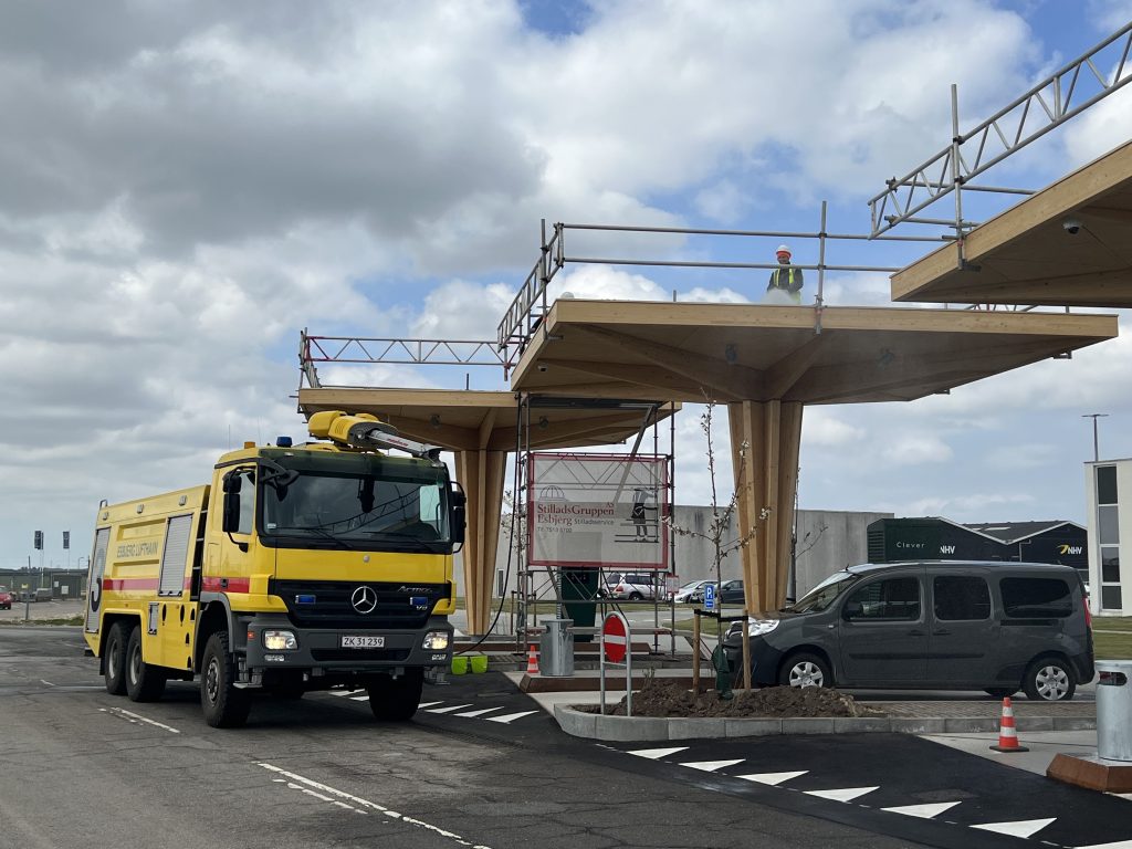
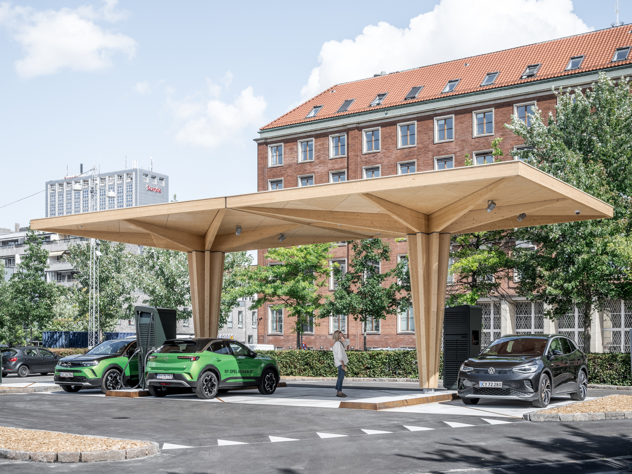
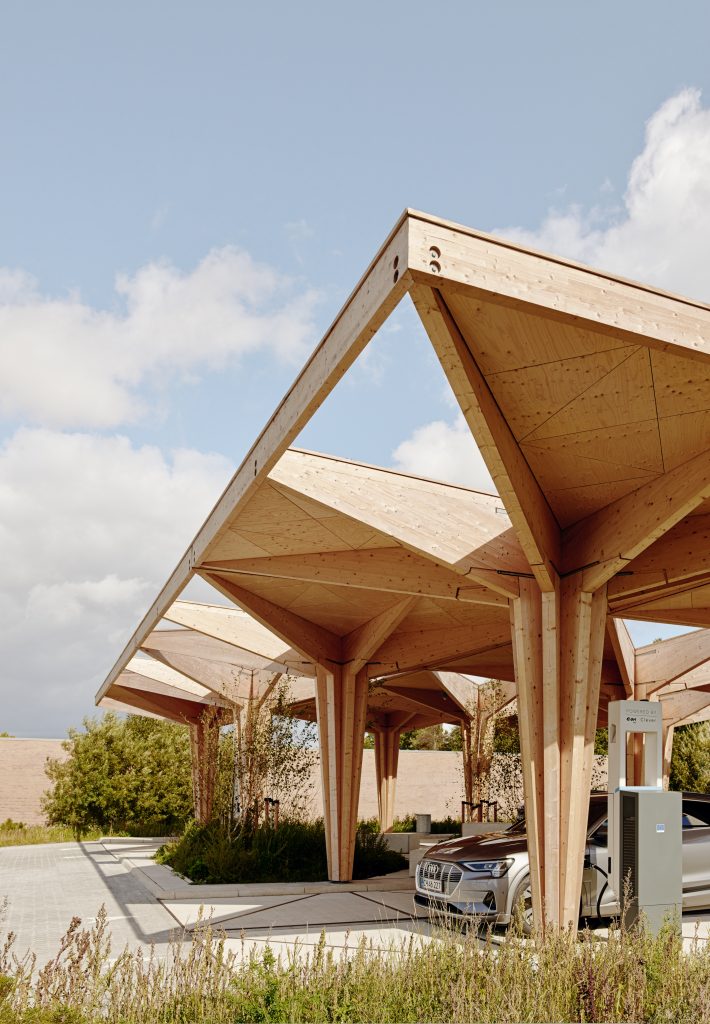
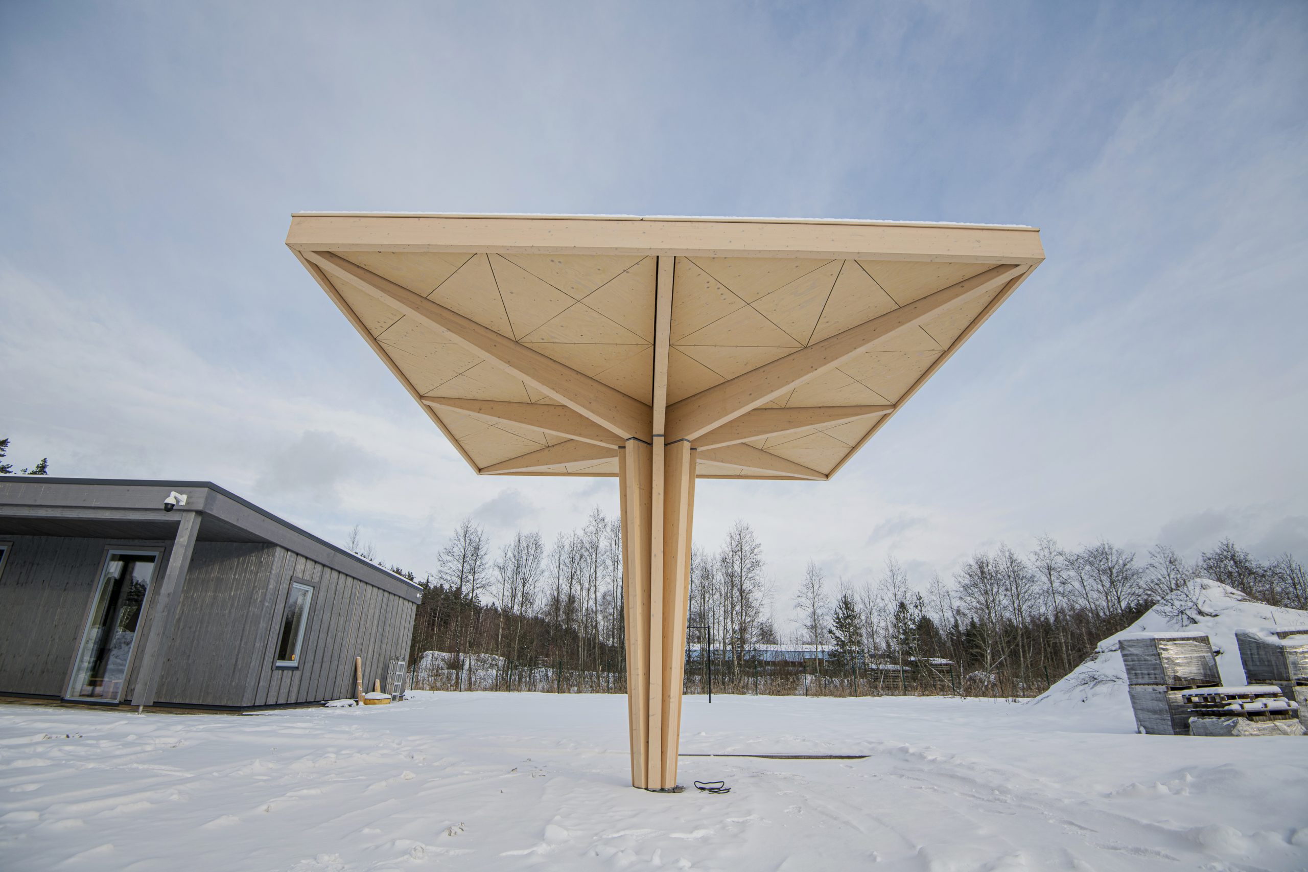
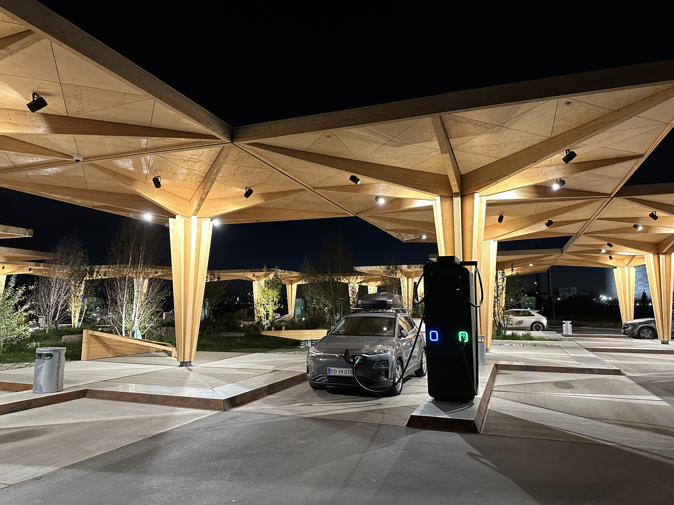
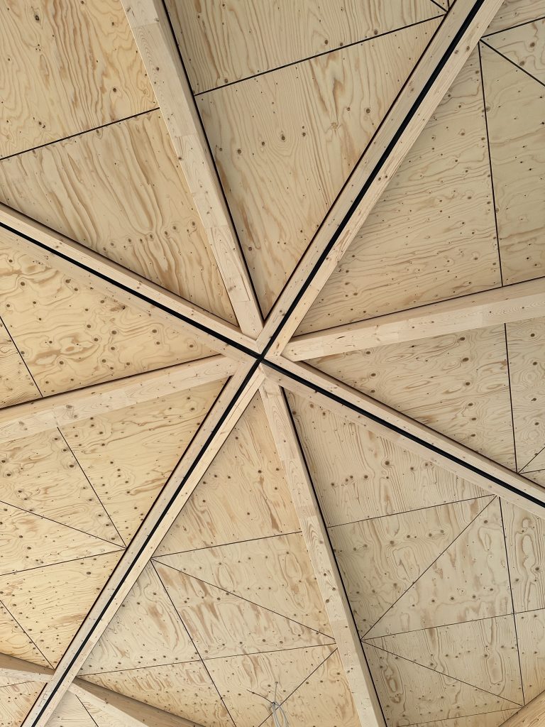
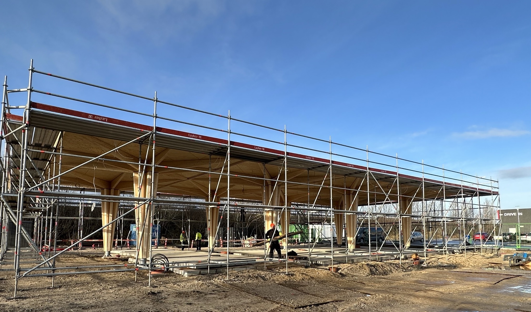
The project was developed by Clever in collaboration with the Danish architectural firm Cobe. At the center of the concept is a five-meter high and seven-meter long and wide roof module, under which there are charging points for cars. The roof modules are interconnected – the modular approach allows to build stations of different sizes and change the configuration.
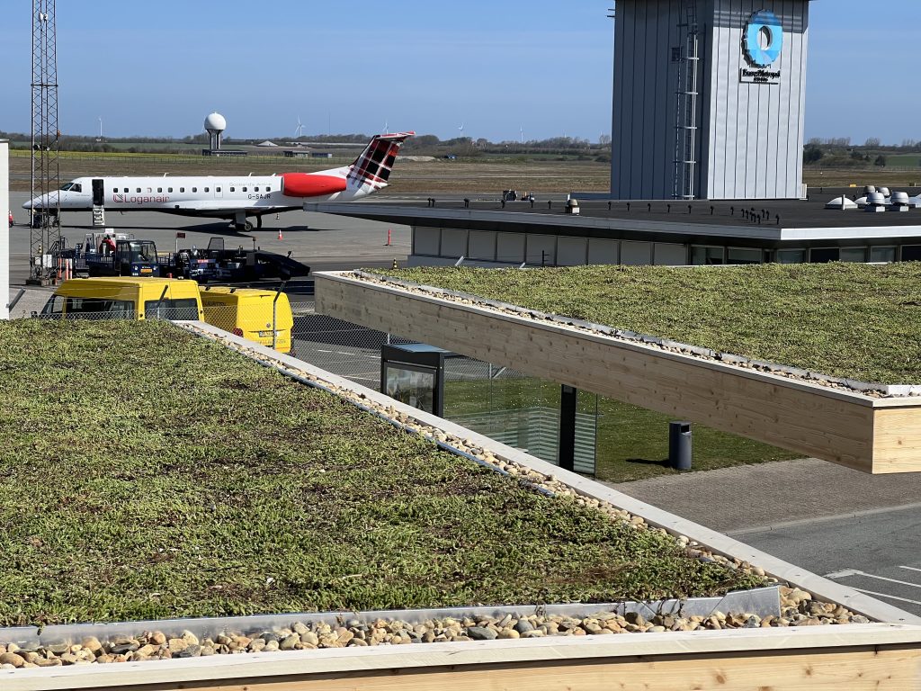
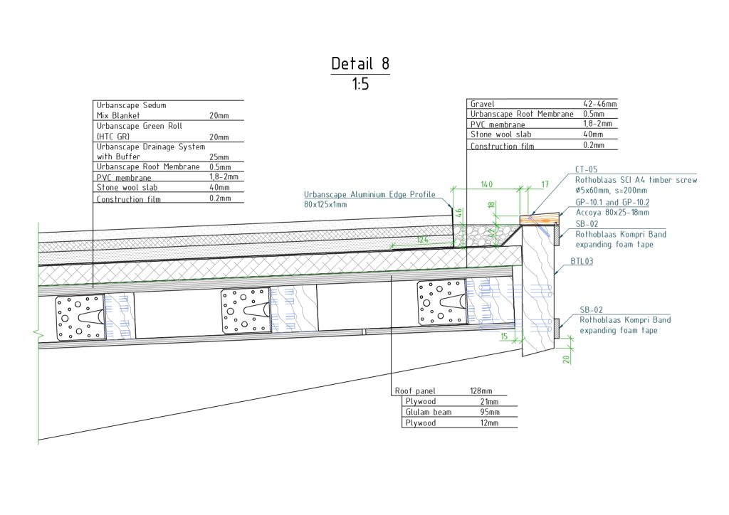
Use of natural materials in the stations is at the centre of Cobe and Clever’s architectural concept and design. The timber building has an extensive green sedum roof with plants typical of the German/Danish region. Timber structures are designed and processed in such a way as to ensure their longevity and preserve the texture of the wood.
DESIGN AND PROTOTYPE
The design was carried out by the Danish company ABC Rådgivende Ingeniører (formerly: AB Clausen). ZAZA TIMBER Engineering, the design and engineering company of the ZAZA TIMBER group, from an early stage assisted the designers by advising on connection solutions, detailing of the building structures, and designing roof panels and their fasteners.
Major additions to the original project
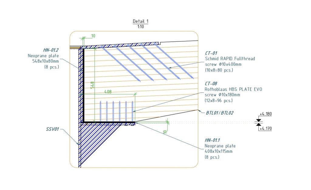
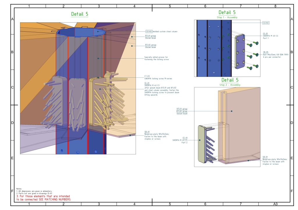
- A solution with high-strength fully threaded screws was used to connect the tensile zone of the narrow cantilevered beam with the steel part.
- The direction of the cantilevered beam’s grain was changed (so it would be parallel to the top part instead of bottom part) so there would not be cross-cut grain in the tensile zone. This approach improves the load-bearing capacity and increases safety.
- Other connections were also improved using more modern hidden connections.
- For the central column, we chose to use a special steel which can be coated with a zinc layer more than 200 microns thick, which improves the longevity of the steel.
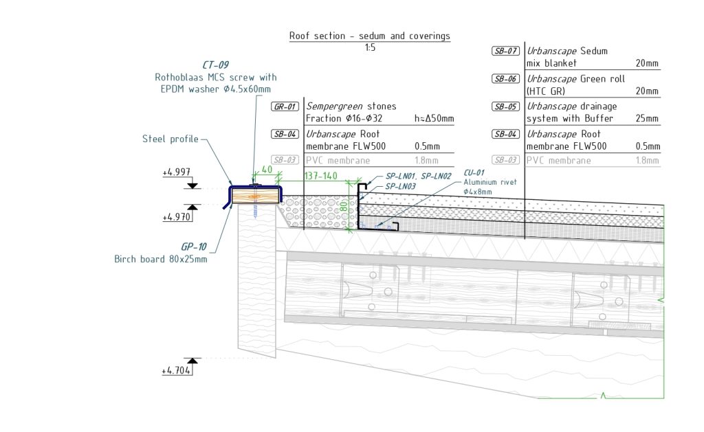
- For timber parts most exposed to the elements, we used Accoya acetylated wood.
- As the dimensions of the sides of the structure increased from 5.6 m to 7 m, we developed new detailing.
- The position and direction of the screws were changed so that the screws covering the fixing points of the roof edges were not visible. As a result, it was possible to maintain a visually perfect outer edge, while gaining the ability to use longer screws increased the load-bearing capacity of the joints.
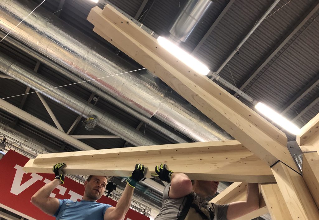
Before starting the construction project, ZAZA TIMBER made and built a prototype of one roof module on the company’s territory. The client was able to verify the company’s ability to implement such projects and the quality of work.
PROJECT DEVELOPMENT
In two years, from December 2020 to the end of 2022, we built 70 canopies.
Aarhus (Denmark) – 1
Frederiksberg (Denmark) – 2
Hallingby (Norway) – 2
Evje (Norway) – 2
Køge (Denmark) – 11
Odense (Denmark) – 28
Esbjerg (Denmark) – 4
Thised (Denmark) – 3
Copenhagen (Denmark) – 5
Nørresundby (Denmark) – 9
Vejle (Denmark) -3
In 2023, another 100 canopies are planned to be built.
IMPROVEMENTS IN THE PROJECT (2021-2022)
- Aesthectic aspects
- Corner joints
- Surfaces
- Cladding for a steel column
- Plywood edges
- Availability and economy of materials
- Column and beam connection
- Alternative to Accoya
- Weather protection
- Corrosion prevention
- Roof joints at different levels
- Water drain freezing
- Creating a scale model for promotional usage
- Construction efficiency
- Use of machinery and the construction site
- Waterproofing of the roof
- Laying a sedum roof
AESTHETIC REQUIREMENTS
The requirements of the project authors regarding the visual image of the building – the quality of the surfaces, the appearance of the surfaces and joints – bordered on furniture quality standards, which are difficult to ensure in large timber structures exposed to the effects of the weather. During the development of the project, the customer identified several aspects where improvements were needed. ZAZA TIMBER construction and design companies worked on solving them.
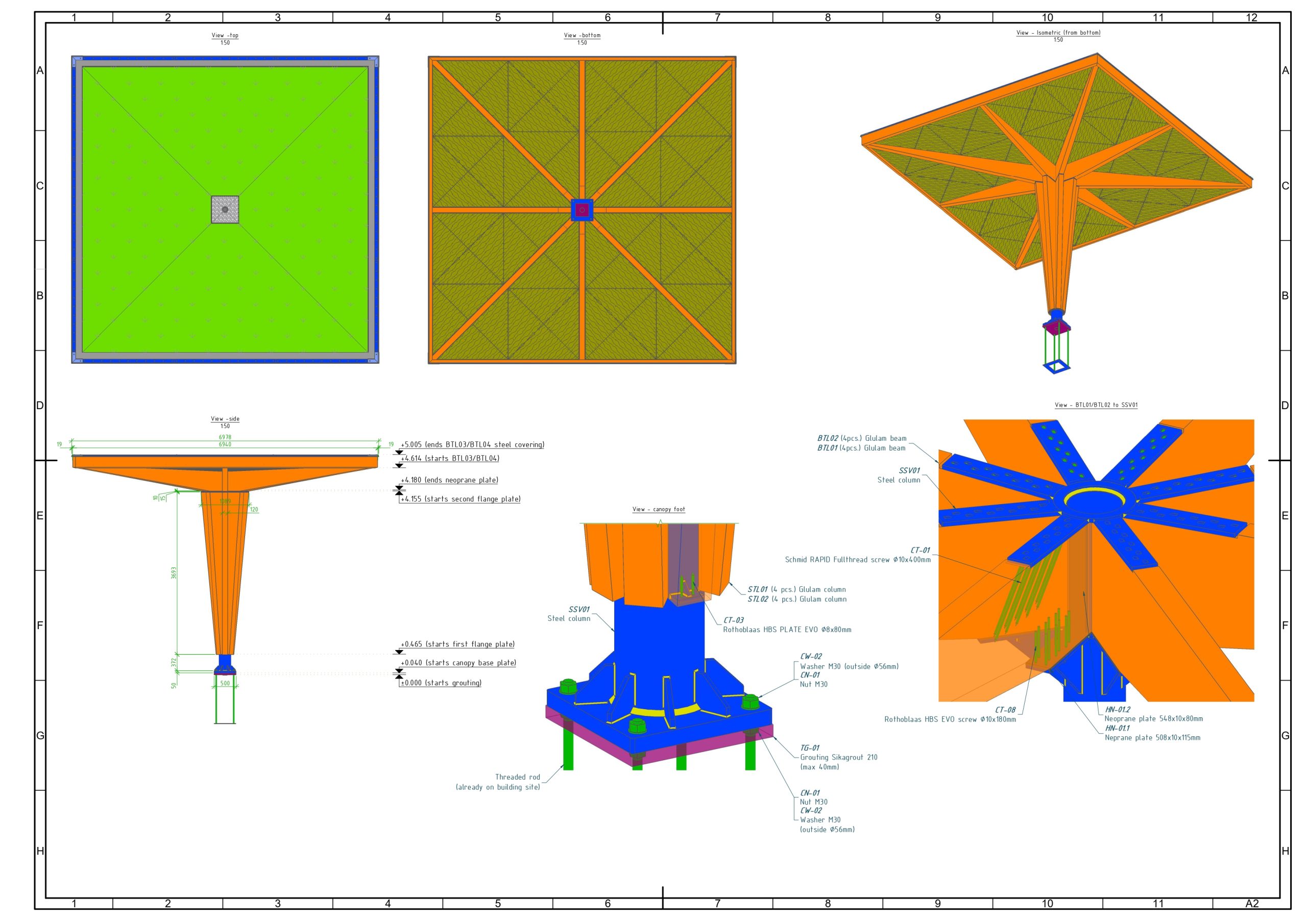
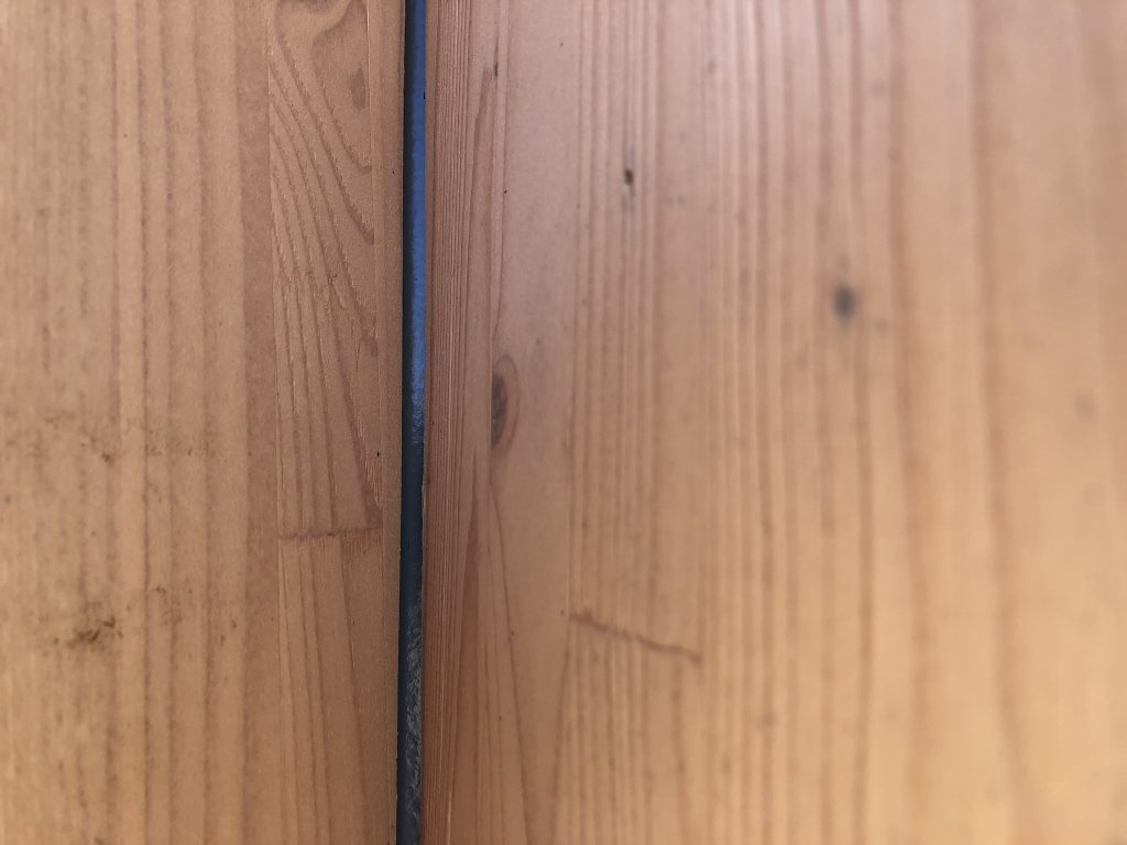
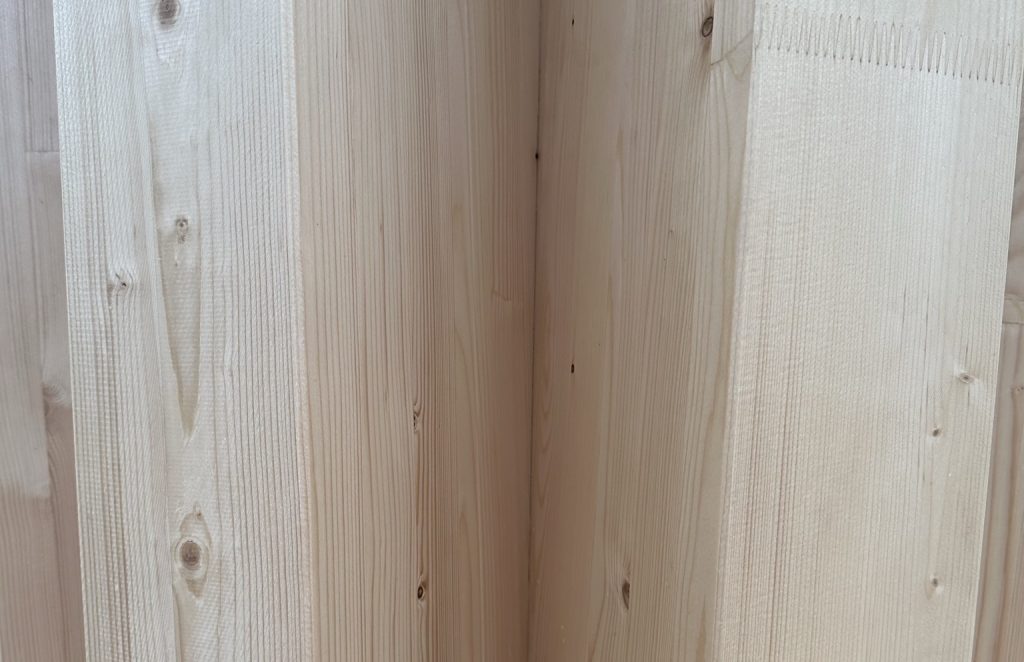
Accuracy of corner joints
The seven-meter-long side beams of the roof connect at the corners at an angle of 45 degrees.
- With such long beam lengths and four corner joints, it is difficult to create an exact square with perfectly fitting miter-joints across the entire cross-section. They are significantly affected by the smallest variance in manufacturing – a millimeter shift in the length or angle of the end cut, or a deviation in the assembly process.
- We solved this problem as follows. Three beams are made to the length specified in the project with a 45-degree cut at the ends, but for the fourth beam one end is left longer so that it can be cut as required. The first three joints are miter-jointed, then the final miter-joint is sawn and machined to the required length and angle.
Surfaces
Glulam structures are usually manufactured to structural standards, not furniture standards.
- The EN14080:2013 standard for glued laminated timber structures allows for various visual imperfections, which do not affect the load-bearing capacity of the structures – tears, unevenness, gaps, smears. On the other hand, customers’ expectations for visual quality are higher, especially in cases where the structures are intended to be exhibited in sight or without special treatment.
- In this project, the client had high requirements for the surface finish, so we ensured the sanding before surface treatment we used colourless priming and finishing with semi-matt transparent wood protection paint.
Column cladding
Covering a circular surface with timber cladding while maintaining the shape of a circle is challenging, as wooden structures slightly change their shape under the influence of the atmosphere. Also, their shape and thus also juncture is affected by roof structure movements, swaying, etc. As a result, occasionally gaps occurred in places between the cladding parts, through which the metal column in the center of the structure was visible.
There were two solutions to this problem.
- The first solution was to cover the column only when all the work on the roof was finished, because the construction workers walking on the roof and loading the materials created an uneven load on the roof beams and was further transferred to the column cladding.
- The second solution was to create a slope for the cladding parts of the column, so that the edge of one part slightly overlaps the adjacent one in the joint.


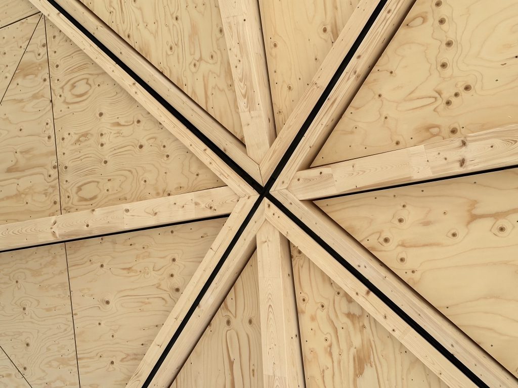
Roof panel juncture
The bottom of the roof panels is made of several triangular-shaped spruce plywood, which is fastened to the edges of the frame.
Where the loose plywood edges met, they began to warp.
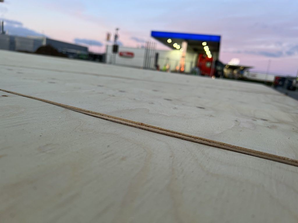
- The issue was solved by improving the design of the panels – in the places where the unsecured plywood edges meet, crossbars common to both edges were placed under them, to which the relevant edges were screwed.
AVAILABILITY OF MATERIALS
Several materials originally planned for the project had limited availability complicating the implementation of the project. In response to that we made changes in the design, replacing hard-to-find materials with more accessible ones. Making changes allowed for other improvements as well.
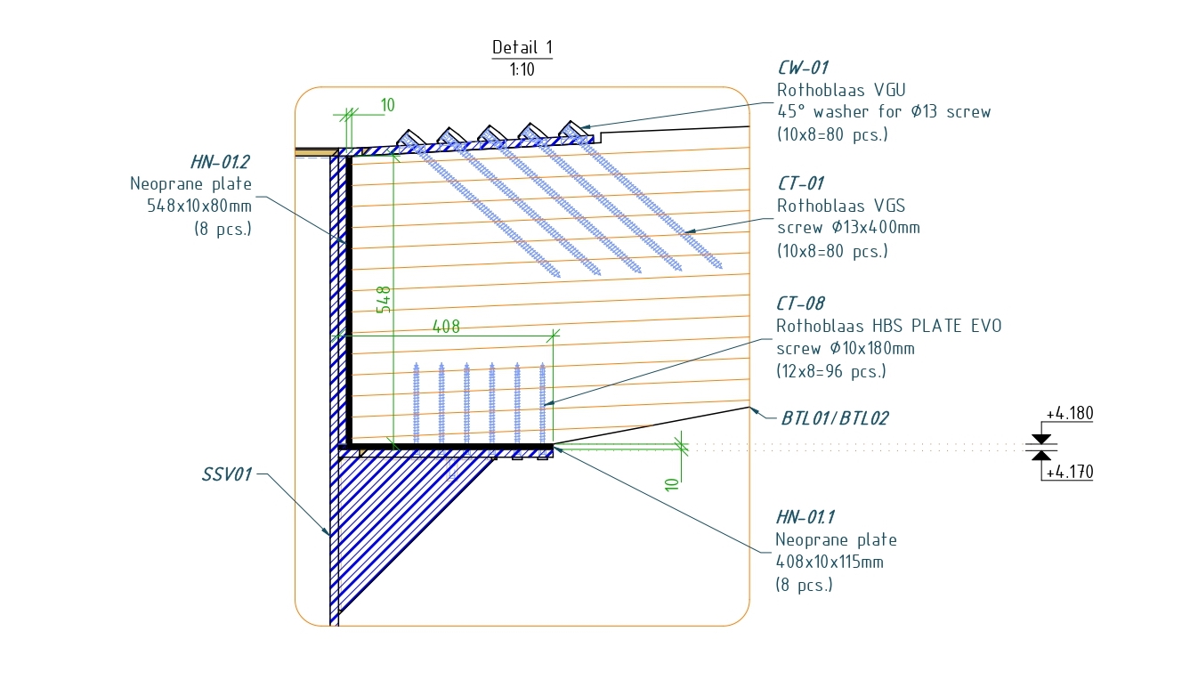
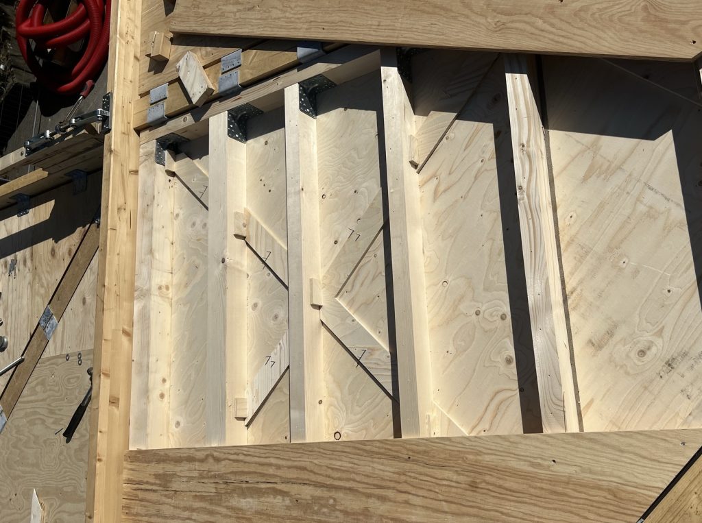
Column and beam moment connection
Each roof beam was attached to the steel flange of the column with 10 screws at a 45° angle, which ensured maximum connection strength.
- In this connection design, we initially included special washers, which provided both a 45° angle and allowed embedding the screw head. Each manufacturer had their own washer and bolt assembly specification, and the washer selected for the project was intended to be used only with the same manufacturer’s 13 mm screws. However, the specific brand of screws or washers were not always available. Additionally, the elevations formed by the washers created inconvenience in laying the roof covering.
- We addressed the issue and found a way to abandon the use of washers and use slightly thinner 10 mm screws, while maintaining the load-bearing capacity of the connection: a special hole at a 45° angle was designed in the steel flange at top of the joint of the steel column and a way to implement it was found in cooperation with the steel part manufacturer.
Alternative to Accoya
In this project, the only timber parts fully exposed to direct precipitation are the boards that secure the edges of the roof membrane above the side beams.
- We originally designed the use of boards made from acetylated wood known as Accoya. However, during the implementation of the project, our assembly unit encountered situations where Accoya was not easily available. On the other hand, ordinary pine or spruce wood is much more susceptible to the effects of precipitation and needs special protection.
- Abandoning Accoya in favor of conventional pine or spruce wood, galvanized steel cladding was chosen for the structural protection of the upper edge of the structures. Its color matched the lower, exposed edge of the galvanized column. Where the edges of the two roof modules are next to each other, they were covered with a common cladding structure.
MITIGATION OF ENVIRONMENTAL IMPACT
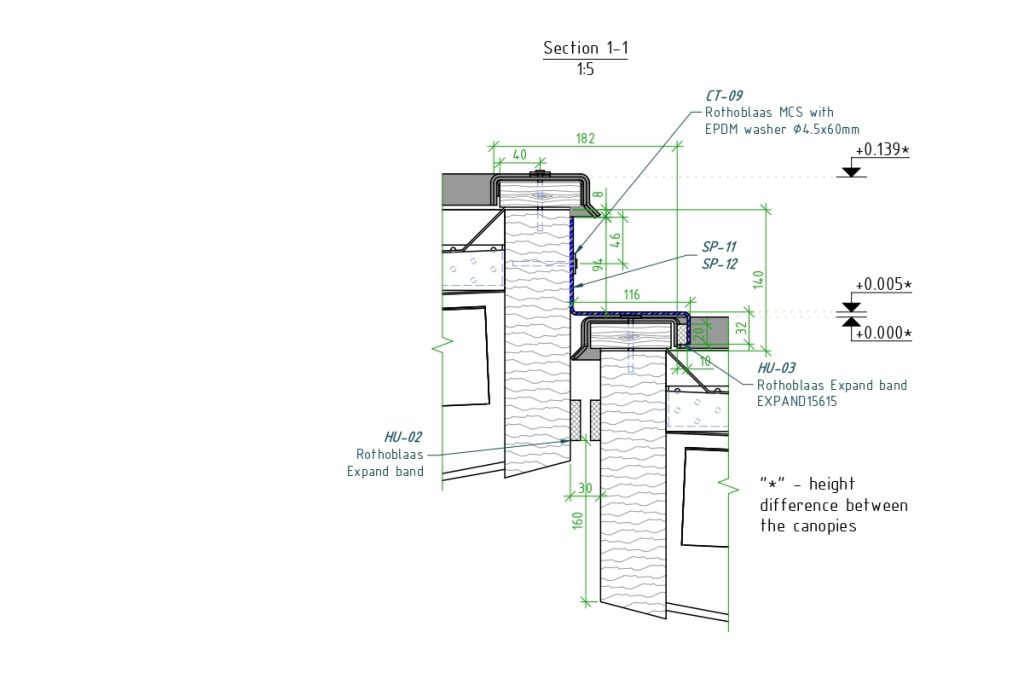
Roof joints at different levels
- In places where the roof modules were next to each other at different heights, there was a gap through which water flowed down during rain.
- We solved this issue by designing and making a common cladding made of galvanized steel for both adjacent roof edges. It covered the gap and led the water to the drain.
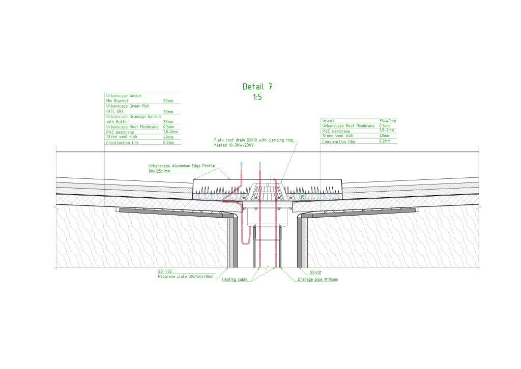
A solution to the freezing of water drains
- Canopies that are installed in areas with low temperatures and high snowfall are at risk of the water drain freezing and the amount of snow and ice accumulating on the roof exceeding the design load.
- To prevent this, we supplemented the project with antifreeze cables that can be installed both in the water drainage pipe inside the column and in the water collection collector.
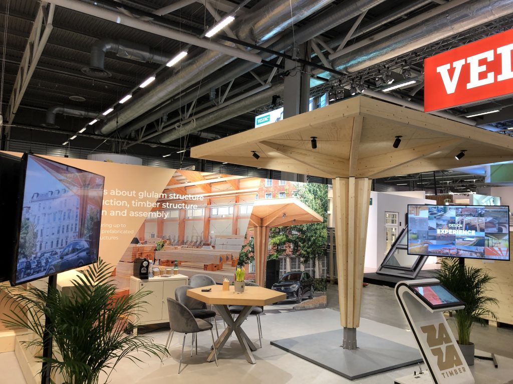
CREATION OF A SCALE MODEL
In order to showcase electric car charging stations at public events, Clever ordered a replica of the canopy in a smaller size – easy to install, dismantle, transport and exhibit even outdoors – in moderate wind.
- ZAZA TIMBER design team developed a scale model with a height of 2.6 meters and 3 meters along the roof edges. The steel column could be disassembled into two parts, sliding joints were chosen to fasten the roof beams, roof edges and column cladding to the column, which allowed to assemble the supporting parts of the structure without using screws. The screws were only needed to attach the plywood to the bottom of the roof.
- The stability of the structure was ensured by a heavy metal plate on which the column was fixed.
- ZAZA TIMBER production and construction companies ensured the manufacture of all structures. The canopy can be assembled and disassembled in a few hours; the work can be done by two people.
EFFICIENCY OF CONSTRUCTION WORKS
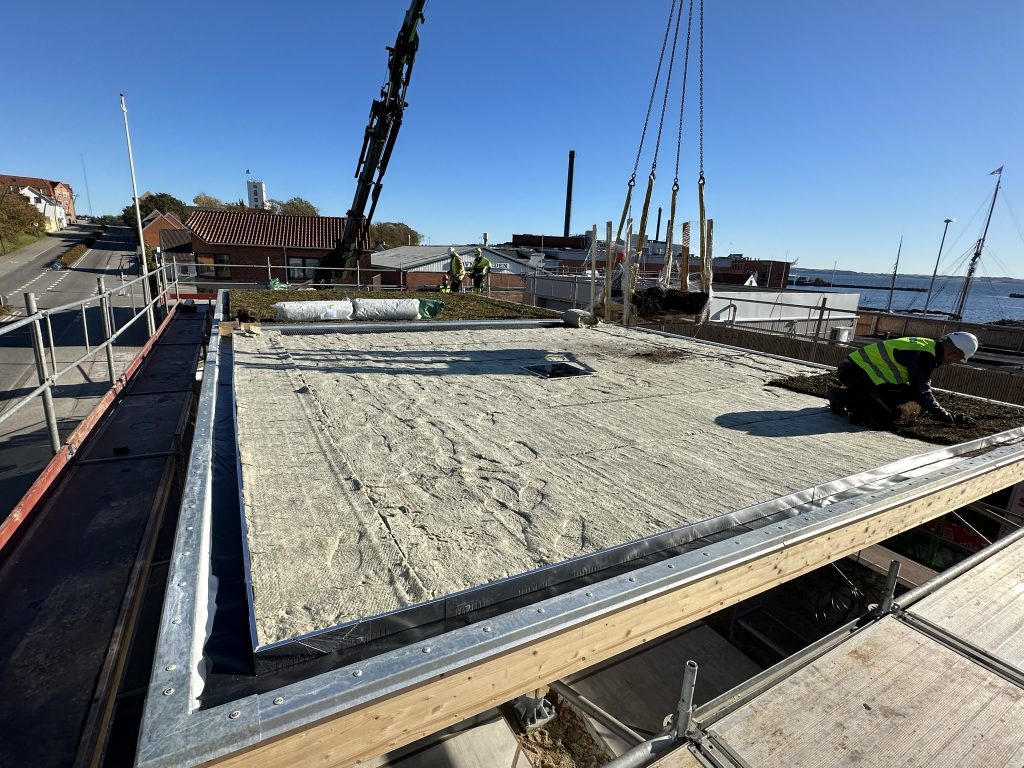
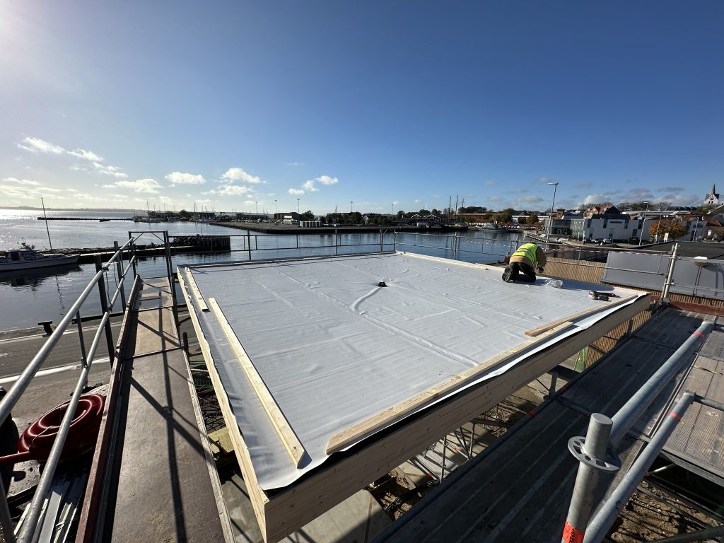
Roof waterproofing
- When building the first canopy, fusible bitumen rolls were used for waterproofing the roof panels. However, working with open fire on wooden structures and often in the wind created a fire safety risk.
- Due to these and other considerations, bitumen was replaced in the project with a more modern material – a membrane. The choice of membrane also made it possible to ensure a higher application quality by using welding equipment that device regulates the melting temperature and speed according to the type of membrane and the air temperature.
Use of machinery and the construction site
During the implementation of the project, we improved the construction efficiency.
- As several canopies are usually built in one place the use of costly lifting equipment was reduced by carrying out the work involving heavy machinery in the first place – column assembly, beam, panel assembly, lifting and placing building materials on the roof level. After that, using only scafolding, we carried out other works that no longer required lifting. This approach also made it possible to give more space to other contractors. We prepared for it already during production and packaging. For each roof structure, all the parts are assembled separately and properly fastened, so that they can be safely and quickly erected on the roof in batches.
- Also, the factory remeasured each timber part and recorded even the smallest deviations in a specially prepared form, so that during assembly it is possible to plan how to place the parts more efficiently, taking into account the permissible deviations.
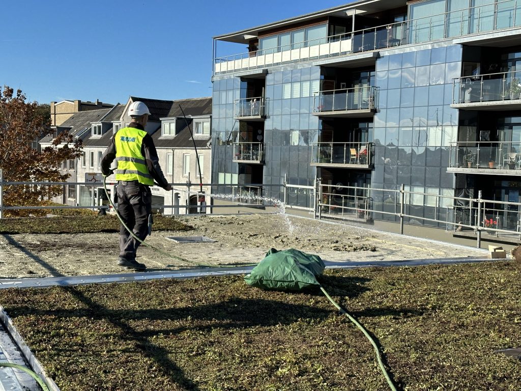
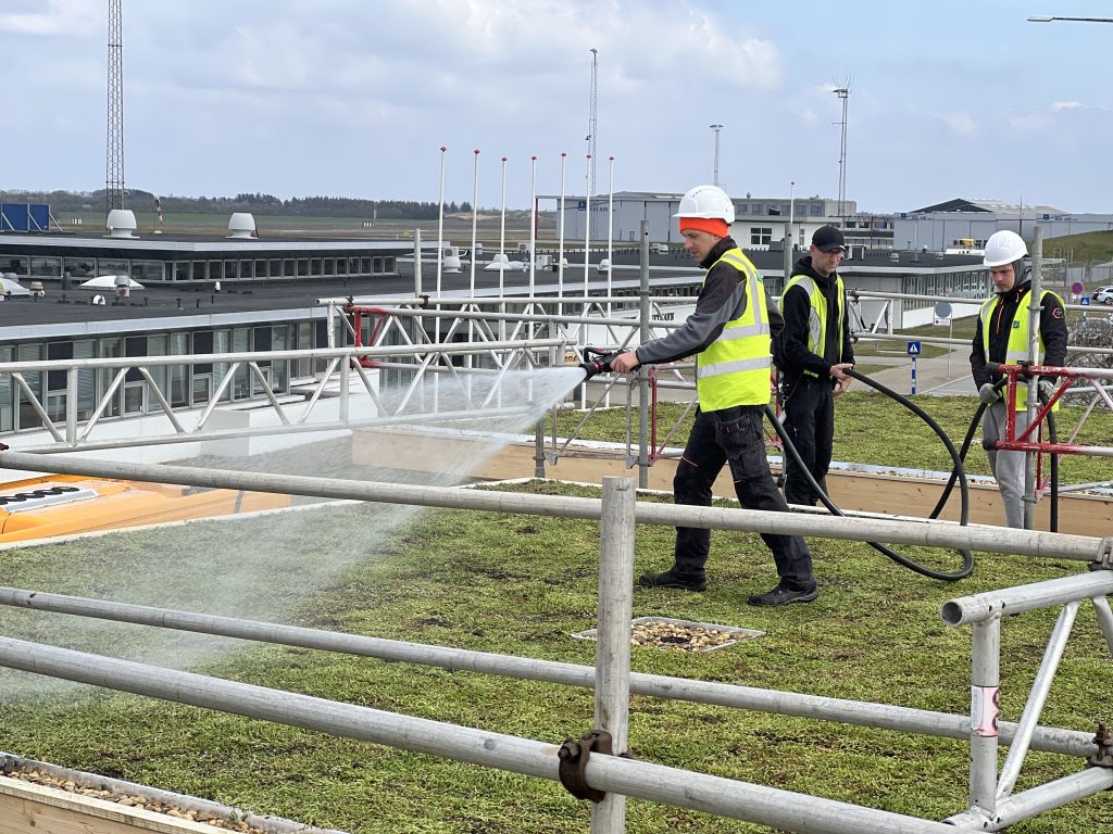
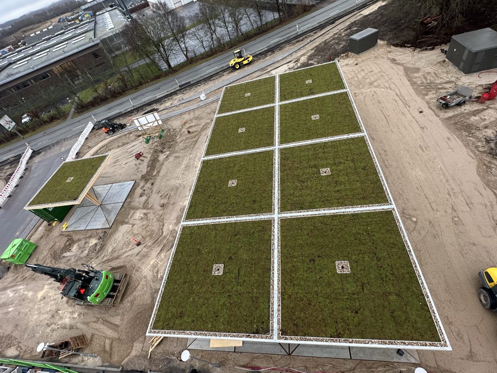
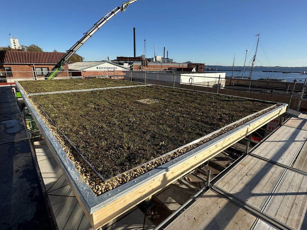
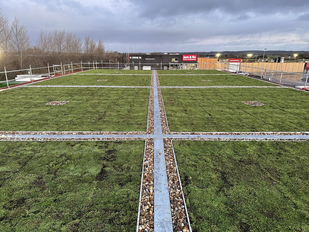
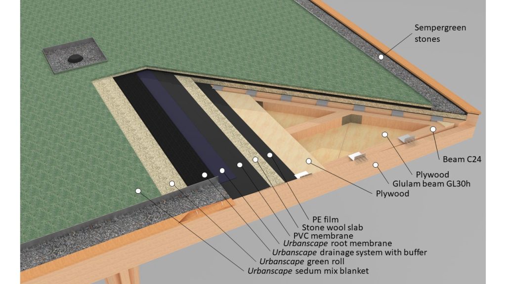
Laying a sedum roof
The roof covering is designed as an extensive green sedum.
- Although sedum requires minimal maintenance, it is important to store it properly before application and apply it correctly. We learned the necessary nuances, how to store the roof before application, when to apply the roof, how to prepare the surface before application and how to perform the initial maintenance of the applied roof.